Ignition Module
The Maverick originally had points. The 302 I got from the 1978 F-150 had a Duraspark II electronic ignition. So I had to figure out how to retro fit it into the car.

This is the ignition module. It is the “brains” of the system. This one has a blue connector. Seems there are others with green and brown. The are all wired different.
Another difference is the distributer cap. The one on the right is original and uses points. The one on the left is what an electronic ignition uses.
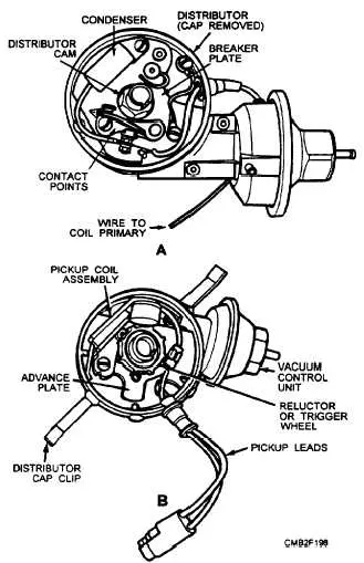
Also the inside of the distributor is diff. The top is points and the bottom is electronic.
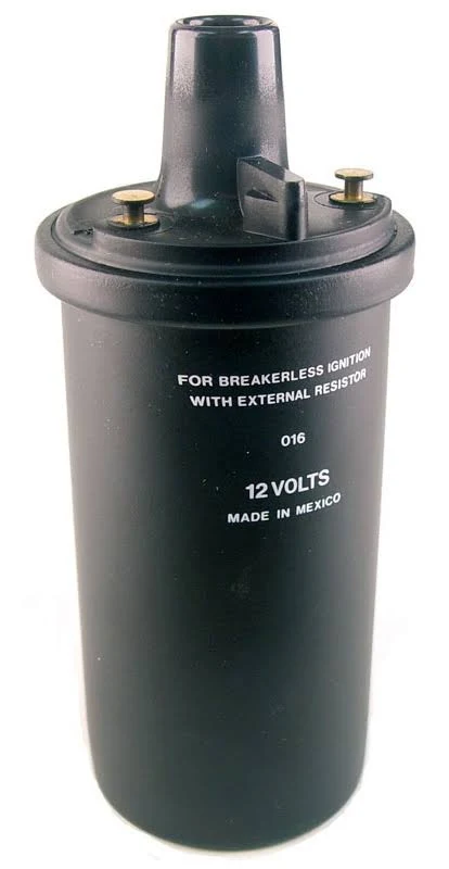
Also need a different coil. This was my best guess. There are soooo many and some need external resistors, some dont. Some work on 12V all the time, some 12V and 6V depending on crank.
It took me a while to come up with this. There is just so many different ideas and drawings out there on how to retro fit this thing. This is what I came up with. Ill try to explain my thinking here….
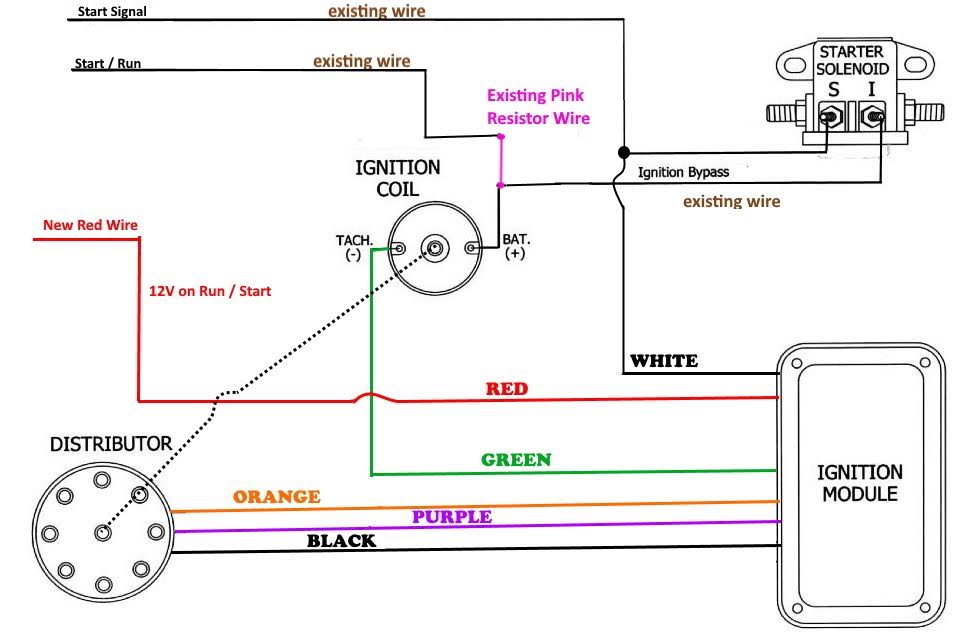
From the distributer to the Module is rather strait forward. Just match up the colors
- A new 12V supply has to be found and run so that the module has power when the car is cranked or running. I believe I can tap this off the #7 accessory fuse.
- The green wire goes to the – (tach) side of the coil
- A white wire is ran to the “S” side of the starter solenoid/relay. This will supply 12V on the white wire to let the module know the car is in cranking mode. After crank the white wire falls to 0V
- There is also a wire already on “S” that is existing from the key switch to send the 12V there when cranking.
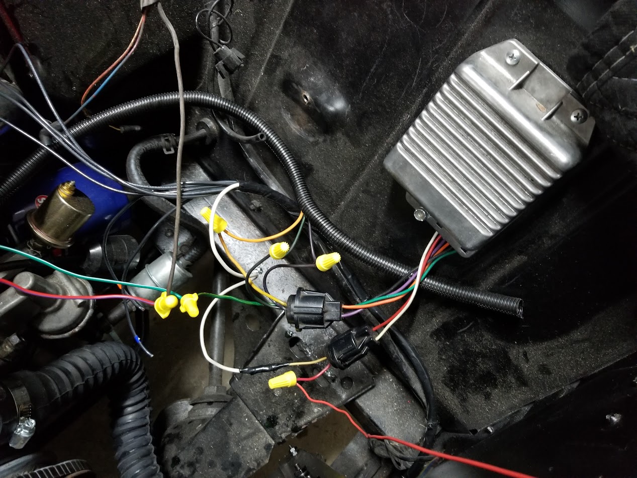
- There is an existing wire on “I” that runs over to the + side of the old coil. Using a multi meter I was able to find which it was coming out of the fire wall and then just patched it into the coil horseshoe
Here you can see the coil horseshoe, with the existing brown wire coming from “I” on the solenoid, and all the wires hooked up at the ignition module. IF and I mean IF this thing starts, I will go back and make them permanent.
Well after messing with it for days, I finally got it to run. The issue is that the plug on the ignition module switches the red and white wire. Why? I have no freaking idea.


You can see here where the wire colors switch. It is actually that way on the ford schematic too. Once I switched the red and white wires at the battery and solenoid , everything worked fine. Ill probably switch them back, as I like red for 12V+, and swap them at the plug end instead.